S Series Heat Pump
| Model Name | PUMY-SP100VKM | PUMY-SP125VKM | PUMY-SP140VKM | ||
|---|---|---|---|---|---|
| Power Source | 1-Phase, 220/230/240 V, 50Hz; 1-phase 220 V, 60Hz | ||||
| Cooling Capacity(Nominal) | kW | 11.20 | 14.00 | 15.50 | |
| Btu | 38214 | 47768 | 52886 | ||
| Power Input | kW | 2.78 | 3.84 | 4.70 | |
| Current Input | A | 12.89-12.33-11.82, 12.89 | 17.81-17.04-16.33, 17.81 | 21.80-20.85-19.98, 21.80 | |
| EER | kW/kW | 4.03 | 3.65 | 3.30 | |
| Temp. range of cooling | Indoor | W.B. | 15 to 24 C (59 to 75 F) | ||
| Outdoor | D.B. | -5 to 52 C (23 to 126 F) | |||
| Heating Capacity(Nominal) | kW | 12.5 | 16.0 | 16.5 | |
| Btu | 42650 | 54592 | 56298 | ||
| Power Input | kW | 2.58 | 3.90 | 4.02 | |
| Current Input | A | 11.97-11.45-10.97,11.97 | 18.09-17.30-16.58,18.09 | 18.65-17.83-17.09, 18.65 | |
| COP | kW/kW | 4.84 | 4.10 | 4.10 | |
| Temp. range of cooling | Indoor | W.B. | 15 to 27°C (59 to 81°F) | ||
| Outdoor | D.B. | -20 to 15°C (-4 to 59°F) | |||
| Indoor unit connectable | Total capacity | 50 to 130% of outdoor unit capacity | |||
| Model/Quantity | CITY MULTI | 15–125/7 | 15–140/10 | 15–140/12 | |
| Sound pressure level(Cooling/Heating) (measured in anechoic room) |
dB(A) | 51/54 | 53/56 | 54/56 | |
| Refrigerant piping diameter | Liquid pipe | mm(in.) | 9.52(3/8) | ||
| Gas pipe | mm(in.) | 15.88(5/8) | |||
| FAN | Type x Quantity | Propeller Fan × 1 | |||
| Airflow rate | m3/min | 75 | 81 | ||
| L/s | 1,283 | 1,383 | |||
| cfm | 2,791 | 2,931 | |||
| Motor output | kW | 0.20 x 1 | |||
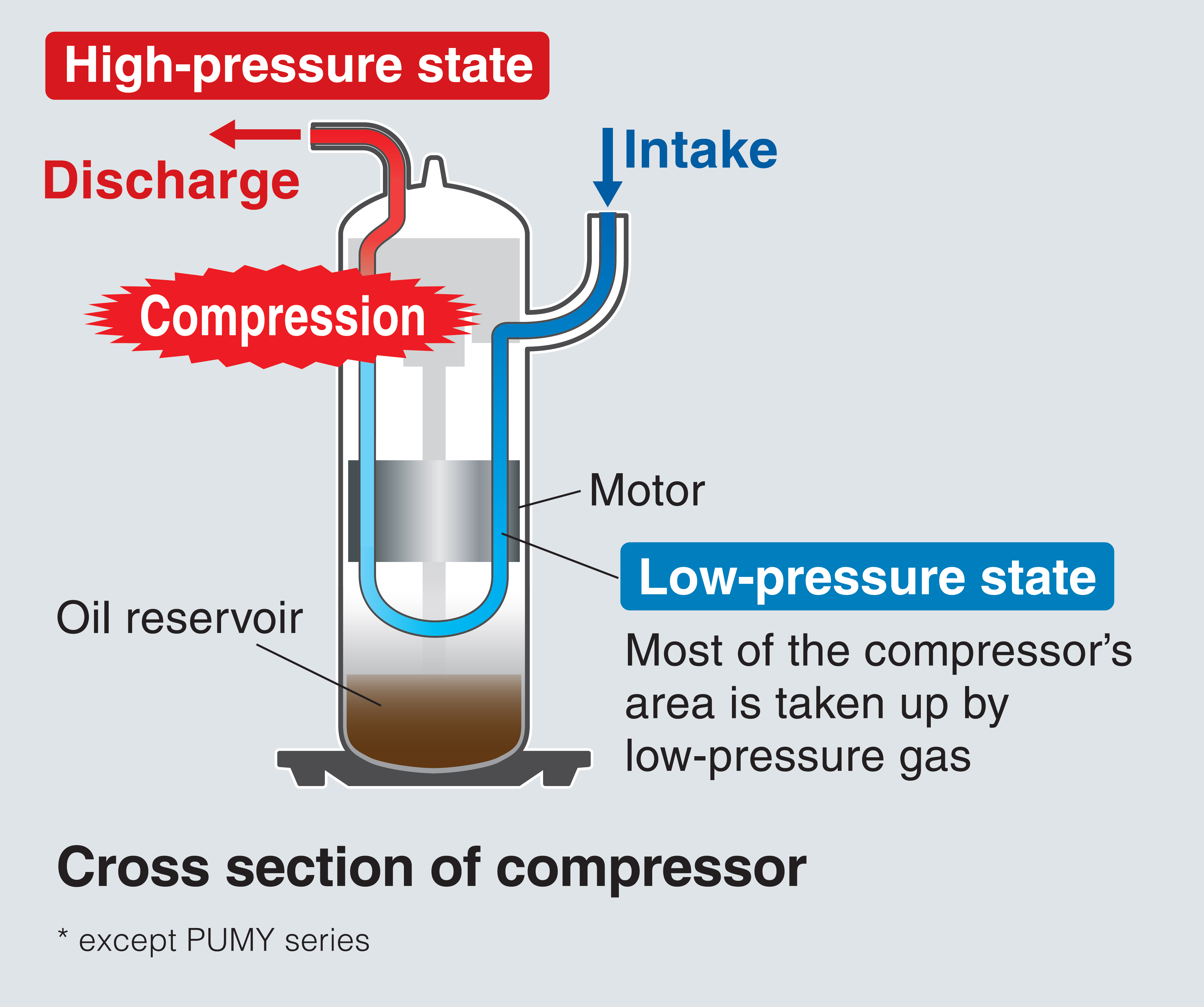
| Compressor | Type x Quantity | Twin rotary hermetic compressor × 1 | |||
| Starting method | Inverter | ||||
| Motor output | kW | 2.7 | 3.5 | 3.7 | |
| External finish | Galvanized Steel Sheet Munsell No. 3Y 7.8/1.1 | ||||
| External Dimension HxWxD | mm | 981 × 1050 × 330 (+25) | |||
| in. | 38-5/8 × 41-3/8 × 13 (+1) | ||||
| Protection devices | High pressure protection | High pressure switch | |||
| Inverter circuit (COMP./FAN) |
Overcurrent detection, Overheat detection (Heat Sink thermistor) | ||||
| Compressor | Compressor thermistor, Overcurrent detection | ||||
| Fan motor | Overheating, Voltage protection | ||||
| Refrigerant | Type x original charge | R410A 3.5kg | |||
| Net weight | kg/lbs | 93 (205) *7 | |||
| Heat Exchanger | Cross Fin and Copper tube | ||||
| Defrosting method | Reversed refrigerant circuit | ||||
| Optional parts | Joint: CMY-Y62-G-E, Header: CMY-Y64/68-G-E, Air protect guide:PAC-SH95AG-E | ||||


S Series Cooling Only
| Model Name | PUMY-CP100VKM | PUMY-CP125VKM | PUMY-CP140VKM | ||
|---|---|---|---|---|---|
| Power Source | 1-phase 220-230-240 V, 50 Hz; 1-phase 220 V, 60 Hz | ||||
| Cooling Capacity(Nominal) | kW | 11.20 | 14.00 | 15.50 | |
| Btu | 38200 | 47800 | 52900 | ||
| Power Input | kW | 2.80 | 3.84 | 4.70 | |
| Current Input | A | 12.99-12.42-11.90, 12.99 | 17.81-17.04-16.33, 17.81 | 21.80-20.85-19.98, 21.80 | |
| EER | kW/kW | 4.00 | 3.65 | 3.30 | |
| Temp. range of cooling | Indoor | W.B. | 15 to 24°C (59 to 75°F) | 15 to 24°C (59 to 75°F) | 15 to 24°C (59 to 75°F) |
| Outdoor | D.B. | 10 to 52°C (50 to 126°F) | 10 to 52°C (50 to 126°F) | 10 to 52°C (50 to 126°F) | |
| Indoor unit connectable | Total capacity | 50 to 130% of outdoor unit capacity | |||
| Model/Quantity | CITY MULTI | 15-125/7 | 15-140/10 | 15-140/12 | |
| Sound pressure level *2 (measured in anechoic room) |
dB(A) | 52/- | 53/- | 54/- | |
| Refrigerant piping diameter | Liquid pipe | mm(in.) | 9.52(3/8) | 9.52(3/8) | 9.52(3/8) |
| Gas pipe | mm(in.) | 15.88(5/8) | 15.88(5/8) | 15.88(5/8) | |
| FAN | Airflow rate | m3/min | 78.8 | ||
| L/s | 1313 | ||||
| cfm | 2782 | ||||
| Type x Quantity | Propeller fan x 1 | Propeller fan x 1 | Propeller fan x 1 | ||
| Motor Output | kW | 0.20 x 1 | |||
| Compressor | Type x Quantity | Twin rotary hermetic compressor × 1 | |||
| Starting Method | Inverter | ||||
| Motor Output | kW | 2.2 | 2.7 | 3.0 | |
| External Dimension HxWxD | mm | 981x1050x330(+25) | 981x1050x330(+25) | 981x1050x330(+25) | |
| in. | 38-5/8 × 41-3/8 × 13 (+1) | 38-5/8 × 41-3/8 × 13 (+1) | 38-5/8 × 41-3/8 × 13 (+1) | ||
| Protection devices | High pressure protection | High pressure switch | |||
|
Inverter circuit |
Overcurrent detection, Overheat detection (Heat Sink thermistor) | ||||
| Compressor | Compressor thermistor, Overcurrent detection | ||||
| Fan motor | Overheating, Voltage protection | ||||
| Refrigerant | Type x original charge | R410A 2.9kg | |||
| Net weight | kg/lbs | 86(190) *4 | 86(190) *4 | 86(190) *4 | |
| External finish | Galvanized Steel Sheet Munsell No. 3Y 7.8/1.1 | Galvanized Steel Sheet Munsell No. 3Y 7.8/1.1 | Galvanized Steel Sheet Munsell No. 3Y 7.8/1.1 | ||
| Heat Exchanger | Micro Slit Fin and Copper tube | Micro Slit Fin and Copper tube | Micro Slit Fin and Copper tube | ||
| Optional parts | Joint: CMY-Y62-G-E, Header: CMY-Y64/68-G-E | ||||
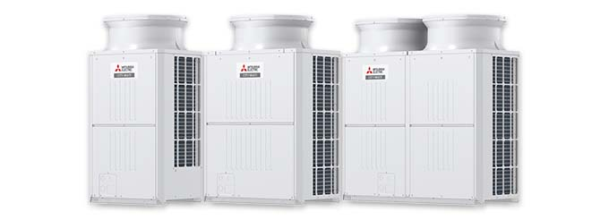
YKD Series Heat Pump
| Model | PUHY-P200YKD (-BS) | PUHY-P250YKD (-BS) | PUHY-P300YKD (-BS) | PUHY-P350YKD (-BS) | ||
|---|---|---|---|---|---|---|
| Power source | 3-phase 4-wire 380-400-415 V 50/60 Hz | 3-phase 4-wire 380-400-415 V 50/60 Hz | 3-phase 4-wire 380-400-415 V 50/60 Hz | 3-phase 4-wire 380-400-415 V 50/60 Hz | ||
| Cooling capacity (Nominal) | *1 | kW | 22.4 | 28.0 | 33.5 | 40.0 |
| kcal/h | 20,000 | 25,000 | 30,000 | 35,000 | ||
| BTU/h | 76,400 | 95,500 | 114,300 | 136,500 | ||
| Power input | kW | 4.48 | 5.88 | 7.59 | 9.66 | |
| Current input | A | 7.5-7.1-6.9 | 9.9-9.4-9.0 | 12.8-12.1-11.7 | 16.3-15.4-14.9 | |
| EER | kW/kW | 5.00 | 4.76 | 4.41 | 4.14 | |
| Temp. range of cooling | Indoor | W.B. | 15.0~24.0 °C (59~75 °F) | 15.0~24.0 °C (59~75 °F) | 15.0~24.0 °C (59~75 °F) | 15.0~24.0 °C (59~75 °F) |
| Outdoor | D.B. | -5.0~52.0 °C (23~126 °F) | -5.0~52.0 °C (23~126 °F) | -5.0~52.0 °C (23~126 °F) | -5.0~52.0 °C (23~126 °F) | |
| Heating capacity (Nominal) | *2 | kW | 22.4 | 28.0 | 33.5 | 40.0 |
| kcal/h | 20,000 | 25,000 | 30,000 | 35,000 | ||
| BTU/h | 76,400 | 95,500 | 114,300 | 136,500 | ||
| Power input | kW | 5.05 | 6.33 | 8.11 | 9.61 | |
| Current input | A | 8.5-8.0-7.8 | 10.6-10.1-9.7 | 13.6-13.0-12.5 | 16.2-15.4-14.8 | |
| COP | kW/kW | 4.43 | 4.42 | 4.13 | 4.16 | |
| Temp. range of heating | Indoor | D.B. | 15.0~27.0 °C (59~81 °F) | 15.0~27.0 °C (59~81 °F) | 15.0~27.0 °C (59~81 °F) | 15.0~27.0 °C (59~81 °F) |
| Outdoor | W.B. | -20.0~15.5 °C (-4~60 °F) | -20.0~15.5 °C (-4~60 °F) | -20.0~15.5 °C (-4~60 °F) | -20.0~15.5 °C (-4~60 °F) | |
| Indoor unit connectable | Total capacity | 50~130% of outdoor unit capacity | 50~130% of outdoor unit capacity | 50~130% of outdoor unit capacity | 50~130% of outdoor unit capacity | |
| Model/Quantity | P15~P250/1~17 | P15~P250/1~21 | P15~P250/1~26 | P15~P400/1~30 | ||
| Sound pressure level(measured in anechoic room) | dB | 57 | 58 | 61 | 61 | |
| Refrigerant piping diameter | Liquid pipe | mm (in.) | 9.52 (3/8) Brazed | 9.52 (3/8) Brazed (12.7 (1/2) Brazed, farthest length >= 90 m) | 9.52 (3/8) Brazed (12.7 (1/2) Brazed, farthest length >= 40 m) | 12.7 (1/2) Brazed |
| Gas pipe | mm (in.) | 22.2 (7/8) Brazed | 22.2 (7/8) Brazed | 22.2 (7/8) Brazed | 28.58 (1-1/8) Brazed | |
| Fan | Type x Quantity | Propeller fan x 1 | Propeller fan x 1 | Propeller fan x 1 | Propeller fan x 1 | |
| Air flow rate | m3/min | 175 | 175 | 185 | 210 | |
| L/s | 2,917 | 2,917 | 3,083 | 3,500 | ||
| cfm | 6,179 | 6,179 | 6,532 | 7,415 | ||
| Control, Driving mechanism | Inverter-control, Direct-driven by motor | Inverter-control, Direct-driven by motor | Inverter-control, Direct-driven by motor | Inverter-control, Direct-driven by motor | ||
| Motor output | kW | 0.92 x 1 | 0.92 x 1 | 0.92 x 1 | 0.92 x 1 | |
| *3 | External static press. | 0 Pa (0 mmH2O) | 0 Pa (0 mmH2O) | 0 Pa (0 mmH2O) | 0 Pa (0 mmH2O) | |
| Compressor | Type | Inverter scroll hermetic compressor | Inverter scroll hermetic compressor | Inverter scroll hermetic compressor | Inverter scroll hermetic compressor | |
| Starting method | Inverter | Inverter | Inverter | Inverter | ||
| Motor output | kW | 5.5 | 6.9 | 8.1 | 10.4 | |
| Case heater | kW | – | – | – | – | |
| External finish | Pre-coated galvanized steel sheets (+powder coating for -BS type) | Pre-coated galvanized steel sheets (+powder coating for -BS type) | Pre-coated galvanized steel sheets (+powder coating for -BS type) | Pre-coated galvanized steel sheets (+powder coating for -BS type) | ||
| External dimension H x W x D | mm | 1,650 x 920 x 740 | 1,650 x 920 x 740 | 1,650 x 920 x 740 | 1,650 x 1,220 x 740 | |
| in. | 65 x 36-1/4 x 29-3/16 | 65 x 36-1/4 x 29-3/16 | 65 x 36-1/4 x 29-3/16 | 65 x 48-1/16 x 29-3/16 | ||
| Protection devices | High pressure protection | High pressure sensor, High pressure switch at 4.15 MPa (601 psi) | High pressure sensor, High pressure switch at 4.15 MPa (601 psi) | High pressure sensor, High pressure switch at 4.15 MPa (601 psi) | High pressure sensor, High pressure switch at 4.15 MPa (601 psi) | |
| Inverter circuit (COMP./FAN) | Over-heat protection, Over-current protection | Over-heat protection, Over-current protection | Over-heat protection, Over-current protection | Over-heat protection, Over-current protection | ||
| Refrigerant | Type x original charge | R410A x 8.0 kg (18 lbs) | R410A x 8.0 kg (18 lbs) | R410A x 8.0 kg (18 lbs) | R410A x 11.5 kg (26 lbs) | |
| Net weight | kg (lbs) | 191 (422) | 191 (422) | 204 (450) | 243 (536) | |
| Heat exchanger | Salt-resistant cross fin & copper tube | Salt-resistant cross fin & copper tube | Salt-resistant cross fin & copper tube | Salt-resistant cross fin & copper tube | ||
| Optional parts | Joint: CMY-Y102SS/LS-G2 | Joint: CMY-Y102SS/LS-G2 | Joint: CMY-Y102SS/LS-G2 | Joint: CMY-Y102SS/LS-G2, CMY-Y202S-G2 | ||

YKD Series Cooling Only
| Model Name | PUCY-P200YKD | PUCY-P250YKD | PUCY-P300YKD | PUCY-P350YKD | ||||
|---|---|---|---|---|---|---|---|---|
| Power Source | 3-phase 4-wire 380-400-415 V 50/60 Hz | |||||||
| Cooling Capacity(Nominal) | kW*1 | 22.4 | 28.0 | 33.5 | 40.0 | |||
| kcal/h | 20000 | 25000 | 30000 | 35000 | ||||
| Btu/h | 76400 | 95500 | 114300 | 136500 | ||||
| Power Input | kW | 4.66 | 5.95 | 7.82 | 9.66 | |||
| Current Input | A | 7.8-7.4-7.2 | 10.0-9.5-9.1 | 13.2-12.5-12.0 | 16.3-15.4-14.9 | |||
| EER | kW/kW | 4.80 | 4.70 | 4.28 | 4.14 | |||
| Temp. range of cooling | Indoor | W.B. | 15 to 24 C (59 to 75 F) | |||||
| Outdoor | D.B. | 10.0~52.0 °C (50~126 °F) | ||||||
| Indoor unit connectable | Total capacity | 50 to 130% of outdoor unit capacity | ||||||
| Model/Quantity | P15~P250/1~17 | P15~P250/1~21 | P15~P250/1~26 | P15~P400/1~30 | ||||
| Sound pressure level(Cooling/Heating) (measured in anechoic room) |
dB(A) | 57 | 58 | 61 | 61 | |||
| Refrigerant piping diameter | Liquid pipe | mm(in.) | 9.52 (3/8) Brazed | 9.52 (3/8) Brazed (12.7 (1/2) Brazed, farthest length >= 90 m) | 9.52 (3/8) Brazed (12.7 (1/2) Brazed, farthest length >= 40 m) | 12.7 (1/2) Brazed | ||
| Gas pipe | mm(in.) | 22.2 (7/8) Brazed | 22.2 (7/8) Brazed | 22.2 (7/8) Brazed | 28.58 (1-1/8) Brazed | |||
| FAN | Type x Quantity | Propeller Fan x 1 | ||||||
| Airflow rate | m3/min | 175 | 175 | 175 | 210 | |||
| L/s | 2917 | 2917 | 2917 | 3500 | ||||
| cfm | 6179 | 6179 | 6179 | 7415 | ||||
| Control, Driving Mechanism | Inverter-control, Direct-driven by motor | |||||||
| Motor output | kW | 0.92 x 1 | ||||||
| External static press. *2 | 0 Pa (0 mmH2O) | |||||||
| Compressor | Type | Inverter scroll hermetic compressor | ||||||
| Starting method | Inverter | |||||||
| Motor output | kW | 5.5 | 6.9 | 8.1 | 10.4 | |||
| External finish | Pre-coated galvanized steel sheets (+powder coating for -BS type) | |||||||
| External Dimension HxWxD | mm | 1,650 x 920 x 740 | 1,650 x 1,220 x 740 | |||||
| in. | 65 x 36-1/4 x 29-3/16 | 65 x 48-1/16 x 29-3/16 | ||||||
| Protection devices | High pressure protection | High pressure sensor, High pressure switch at 4.15 MPa (601 psi) | ||||||
| Inverter circuit (COMP./FAN) |
Over-heat protection, Over-current protection | |||||||
| Refrigerant | Type x original charge | R410A x 5.5 kg (13 lbs) | R410A x 6.5 kg (15 lbs) | R410A x 6.5 kg (15 lbs) | R410A x 11.5 kg (26 lbs) | |||
| Net weight | kg/lbs | 174 (384) | 183 (404) | 200 (441) | 236 (521) | |||
| Heat Exchanger | Salt-resistant cross fin & copper tube | |||||||
| Optional parts | Joint: CMY-Y102SS/LS-G2 | Joint: CMY-Y102SS/LS-G2 | Joint: CMY-Y102SS/LS-G2 | Joint: CMY-Y102SS/ LS-G2,CMY-Y202S-G2 | ||||

